By Ben Nitkin on
Something's been bothering me for a while: I don't have a proper tail light on my bicycle. I used to, but it fell off. That was sad, but didn't faze me too much; I don't ride much at night, so I didn't really need the light.
Yesterday, I went on a ride around Easton in the dark. Yesterday, I figured out how to push code to AVR's. One and one makes two, and I decided to fabricate myself a taillight based around the ATTiny85.
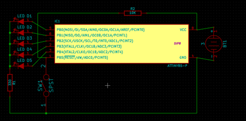
I started by laying out the circuit on a breadboard. I connected each output of the ATTiny85 to a common node with an LED, and connected that node to ground with a 330Ω resistor.
Since LEDs are diodes, the AVR doesn't fight itself to drive some pins high while leaving others low. Using a common resistor means that brightness varies depending on the number of LED's lit, but I don't mind.
I didn't want to waste a pin on a power button, so I wired a button between GND and Reset. Pushing the button resets the chip, which restarts the program from the top.
The program begins by incrementing a counter stored in EEPROM, mod 3. It then tests that byte. If the counter is 0, the light turns off and the chip powers down. If it's 1, the light blinks. If the counter is 2, the light turns on. Resetting the chip restarts the main method, moving the chip from one state to the next. Here's the snippet of code that manages the mode:
int main (void) {
    DDRB = 0xFF;
    //Test for the mode to go into.
    uint8_t mode = eeprom_read_byte(ADDRESS);
    //Increment the mode: 0 -> 1 -> 2 -> 0...
    eeprom_write_byte((uint8_t *) ADDRESS, (mode+1)%3);

    switch (mode) {
        case 0:
        off();
        ...
    }
}
The rest of the code is fairly straightforward, although the blinking function is interesting. The AVR groups all six output pins in the 7-bit register PORTB. (Reset can be configured as a seventh output, but then the chip can't be reset.)
My blinking code continually shifts all bits in PORTB left, adding the negation of the value of the high bit. That's a big sentence, but the result is simple: first, all the lights turn on in order, right to left. Then they turn off, again right to left.
//Blink the LED's in a variable brightness pattern.Once I verified the code on the breadboard, I deadbug soldered the whole thing together. One leg of each LED attached to the chip; the other connected to a common node just behind the microcontroller. The 330Ω resistor connected that node to ground. A big resistor pulled Reset to Vcc, and a pushbutton connected Reset to Gnd (to, y'know, reset).
void blink(void) {
while (1) {
//Shift PortB left; add 1 if the high bit is zero.
//That makes a cylon pattern: on one at a time, then
//off one at a time.
PORTB = (PORTB << 1) + !(PORTB & 0x20);
_delay_ms(100);
}
}
After verifying that the whole thing worked on 3v of power, I potted the mess in hot glue (keeping the button down for light weatherproofing), and attached it to my bike. The lights aren't real bright, but they'll keep me visible in the dark.
