By Ben Nitkin on

Wait a minute. Is gamma not a thing? You have alphas, then betas. So my first proper release will be named gamma. Deal with it.
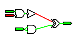
Anyhow, I've cleaned up the simulator a lot since last time. There are a ton of new checks, and some new features, too. Inputs, for instance, will remain associated with Outputs even if a second output is dragged through the binding area.
As far as new features, the simulator now includes grid spacing (Gates jump to line up with each other, so you get pretty right angles). By default, Gates are 30 pixels across. Setting their inputs to be 1/4 of that height apart from each other allows for a grid spacing of 7.5 pixels. There are a few modes: by default, a grid's drawn, and grid spacing is enforced. The grid and spacing can both be disabled, though, for a cleaner mode (no grid drawn) and a freeform one (no spacing enforced).
Wires are back to being one-directional. Bidirectional wires had a nasty habit of associating in both directions: they'd funnel signals strangely at anything but the simplest intersections.
Wires are also much more uniform than before. There aren't any more ugly unions.
Inversion is working for all inputs and outputs.
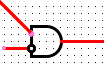
The one remaining bug is gates. I can't figure out the geometry to make a pretty OR gate.
So, without further ado, a quick user manual! Call out the trumpets and the band!
LogicSim II Gamma
ADDITION To add objects to the canvas, press the corrosponding hotkey. All hotkeys are listed in the helptext at the bottom of the screen.
- a And
- r Or
- x Exclusive Or
- n Inverter (think Not)
- w Wire (to connect things!)
- i Input (provides input to the circuit)
- o Output (A flag that shows an output's state)
MOVEMENT To move gates, just click the mouse near the middle of the gate and move it. To move a wire, click near the end, and drag the endpoint.
REMOVAL To remove elements, click on them with the middle mouse button.
INVERSION To invert any input or output, right click on the attachment point (where the purple or green dot was before wires were attached)
USAGE The small purple and green dots on elements are inputs and outputs. Drag outputs near inputs to associate them, or use wires to span longer distances, (purple connects to green and vice versa).
OPTIONS The s key slows the simulation down; S speeds it up (note case). Pressing g rotates through three snapping modes:
- No snapping
- Snapping with grid
- Snapping, no grid
Enjoy! There'll be another version with more features and OR gates soonish.