IGVC

E-Stop

Original E-Stop Circuit
The LRC circuit, up top, runs the show.

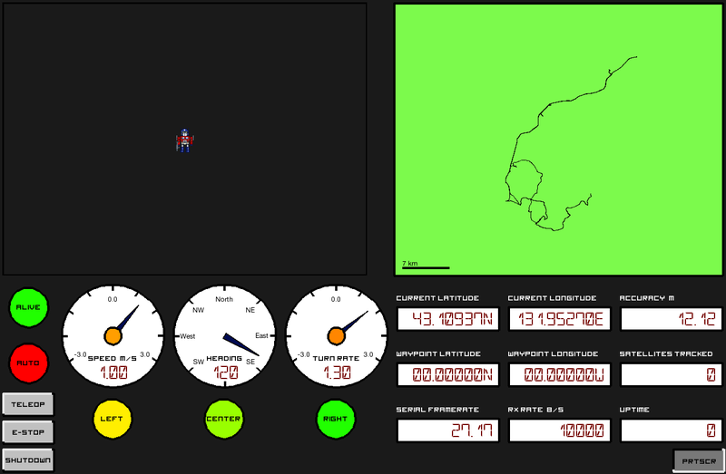
You probably know I'm working on building an autonomous robot as a senior project by now. (Psst. If not, read about it. Here.)

Now, this robot is driven by a pair of horsepower motors. Given full throttle, it'll easily hit 30mph. Even with safeties baked into the autonav code and Arduino motor driver, we need emergency stops. In fact, we have three. One's implemented in the packet radio: we've defined a code that will immediately kill the robot. A button on the robot will cut power to the main relay. The third E-Stop is a hardware radio E-Stop. That's the most interesting one, and I'm going to talk a bit about how it's designed. And since you're such great listeners, you'll listen. Thanks!

The radio E-Stop comes has a few requirements. I'm going to put them in a list, since I just realized that breaking up text makes it easier to read. It must:

  1. not use any software (microcontrollers are presumably banned).
  2. have a range exceeding 100'.
  3. bring the robot to a "quick and complete stop".
  4. be held by the judges during competition.

Okay. The last 'requirement' isn't technical, but it requires the E-Stop to be portable. 

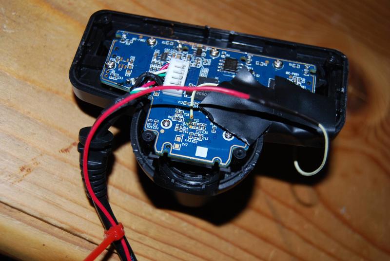
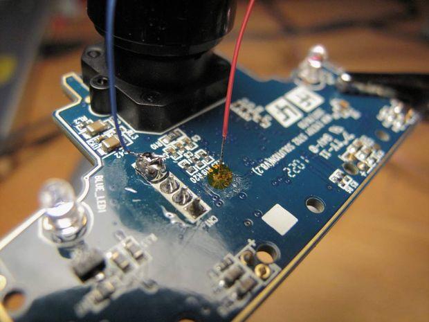
Given those requirements, I started putting together details about the e-stop. It needed a radio good to 100', so I found a cheap transmitter/receiver pair on Sparkfun. They're friendly in that they're easy to use, but that suggests a problem: what if someone else at the competition uses the same radio? We clearly needed some way to distinguish our E-stop from potential random noise. But it can't be too complicated; we're on a deadline and can't use software to distinguish long patterns. 

Base Station

Over the past few weeks, I've been developing a base station for Optimus'. (That's the IGVC robot's name.) In order to operate autonomously, Optimus' is outfit with a slew of sensors. In order to keep tabs on Optimus' and his operation, the base station establishes a radio link with the robot. The robot constantly sends telemetry data out to the base station and the base station periodically sends commands to the robot. 

Divergence Mapping, Mark II

Mark II sounds technical. So is this post. In the last post, I described how divergence mapping works. Fundamentally, divergence mapping creates a 3d image using two cameras, much like the human eye. The link above goes into more detail on our high-level method; this post is about hardware.

Here, you'll learn how to modify a PS3 eye for synchronized images. (Apologies, but I'm shy on pictures of the camera coming apart.)

First, remove all of the screws from the camera's backside. They're all hidden under the round rubber pads, which will pry off with a slotted screwdriver. The screws themselves are all Phillips. 

Next, gently pry the back off of the camera. The board and lens are attached to the front piece of plastic; the back will pull off. The two sides are attached with plastic hooks. I found that needling a slotted screwdriver between the layers of plastic and then twisting worked well. Start at the top, and save the round bottom for last (it's tough to get open).

Divergence Mapping

One of the most important sensors on the robot is a depth sensor, used to pick out obstacles blocking the robot. If the obstacles were uniform, color and pattern matching would suffice, but they're massively varied. The course includes garbage cans (tall, round, green or gray), traffic cones (short, cone, orange), construction barrels (tall, cylindrical, orange), and sawhorses (they look different from every side). Sophisticated computer vision could pick them out, but a depth sensor can easily separate foreground and background. 

Most teams use LIDAR. These expensive sensors send a ping of light and time the echo. Time is converted to distance, and the ping is swept 180 degrees around the robot. We can't afford LIDAR. Our depth-sensing solution is divergence mapping. The sensing works in much the same way as a human eye: two cameras, a small distance apart, capture images synchronously. The images are compared, and their small differences are used to find depth. People do it subconsciously; the computer searches for keypoints (features that it can identify between frames). The matching fails on uniform surfaces, but works well on textured ones. (Like grass; isn't that convenient?)

A depthmap visualized.The depthmap can only be generated when the images match closely. That means that the cameras need to be fixed relative to each other, and the images need to be taken simultaneously.

Approaches

Now that you know what the IGVC is about, I'll go into some detail about our high-level approach. The challenge provides some obvious requirements:

  • A reference frame relative to earth to navigate to waypoints; GPS provides position and compass provides heading
  • Line detection to stay within lanes; a color camera suffices
  • Obstacle detection; a 2D rangefinder is the is logical choice
  • Precise measurement of velocity; provided by encoders, accelerometers, and gyros

I'll go through each requirement in a bit of depth, describe typical solutions, and design constraints. 

An absolute reference tells the robot exactly where in the world it is. GPS and compass provide that data. Unfortunately, GPS is only accurate to about 6', so it isn't useful for local navigation. A 2' difference in position is the difference in hitting an obstacle and avoiding it. The GPS is useful for providing long-range direction: the goal is 60' southwest.

Most teams improve their GPS accuracy with exotic antennas and exact correction services (the speed of light varies through the atmosphere, distorting timestamps and GPS location. A corrective signal provides the difference in true and measured time-of-flight, improving accuracy.) Although these units offer remarkable resolution (within 6"), they are prohibitively expensive ($20,000). 

Lafayette's team, named Team Terminus, will use an inexpensive GPS receiver, accurate to roughly 6'. It costs less than $100. (Cost, by the way, will be a persistent theme. Most IGVC robots run $20,000 to $80,000; Lafayette budgeted Terminus $6000.)

IGVC Introduction

The robot, in profile.
Lookit it! It's our robot!

The robot, in profile. This semester, I was invited to work on a Mechanical Engineering Senior Project. (And yes, I need all of those capital letters.) The team is, with the exception of yours truly, entirely composed of MechE's. I was invited when the team leader spoke with Helen, who in turn suggested that I would be useful, what with my background in FIRST Robotics and Linux. (So many capital letters.)

Each year, the Mechanical Engineering department sponsors a half-dozen senior projects. Each gives a team of engineers some capstone challenge, including SAE Aero Design, Formula Car, and many others. Most of these teams have been around for years; the team one I worked on was brand-new.

IGVC. That's the competition. The competition - the Intelligent Ground Vehicle Competition - challenges teams to design and build robots capable of autonomously navigating a course. Two courses are provided: basic and advanced.