2012 Posts

Custom DDNS

A few years ago, I set up a home server. It runs a few services - mostly MythTV and an FTP server. When I first set it up, I gave it DDNS through DynamicDNS (it was heartofgold.dyndns.com). I became fed up with their policies fairly quickly - especially their expiration rules, and replaced them with afraid.org DNS.

Afraid.org offered free DNS, but the service also has an expiration. I missed a deadline, and my lovely domain (bam.boozle.co) went dark. But now, I have my very own address: nitkin.net, and all of its derivatives. I've wanted to give the home server the address home.nitkin.net for a while, and now I have time to fiddle.

Every computer on the internet has an IP address which identifies it uniquely. But you browse using names, which aren't directly linked to machines. Essentially, when you type an address into the URL bar, various servers recursively evaluate it, looking for an IP address to connect to. For my URL, home.nitkin.net., the request is first passed to a root server. That server looks at the net portion of the URL, and forwards the request for home.nitkin. to the root net server. That server resolves nitkin to a machine owned by IMeanWebHosting, and asks that server to resolve the last part of the URL: home. home resolves to the IP address of my home server, which is returned to you.

(In reality, there's tons of caching going on. As likely as not, searches like en.google.com are common enough that the first server you ask has the IP saved.)

To assign the name, I just needed to add an A (address) record to the nitkin.net nameserver. Adding the record is trivial. Keeping it up to date is harder.
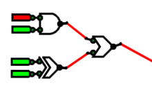
Gamma Logic Gate Simulation

Wait a minute. Is gamma not a thing? You have alphas, then betas. So my first proper release will be named gamma. Deal with it.

Anyhow, I've cleaned up the simulator a lot since last time. There are a ton of new checks, and some new features, too. Inputs, for instance, will remain associated with Outputs even if a second output is dragged through the binding area.

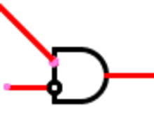
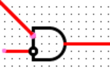
As far as new features, the simulator now includes grid spacing (Gates jump to line up with each other, so you get pretty right angles). By default, Gates are 30 pixels across. Setting their inputs to be 1/4 of that height apart from each other allows for a grid spacing of 7.5 pixels. There are a few modes: by default, a grid's drawn, and grid spacing is enforced. The grid and spacing can both be disabled, though, for a cleaner mode (no grid drawn) and a freeform one (no spacing enforced).

Wires!

One bug down!

I had Gates reassociate their hotspots whenever the gate moved. I also reassociated hotspots whenever they were moved. Problem is, Hotspots are placed relative to Objects, so they never move. The exception is the tail end of the wire. So, the Hotspot on the wire's tail associated fine, but the one connected to the head was never told to reassociate, so it would never connect to anything. Adding a few lines to tell the head to associate too worked perfectly.

Wires are now bidirectional and working!

Working simulation!

This year, in digital circuits, I learned about digital circuits. Surprise. This year in CS, I learned about subclassing, data structures, and program flow. Together, I made a logic simulator.

Fundamentally speaking, digital circuits are made up of discrete components. Ganged together, these simple components are capable of realizing complex tasks.

Beta Logic Gate Simulation

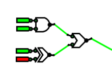
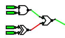
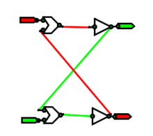
This weekend, I decided to throw out my previous logic simulator and make a new one based on what I'd learned. It's still in beta, but I got it to simulate an SR latch, and I'm proud. I'm going to sleep now, but wanted to tell the world about my success. Latches are awesome.

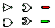
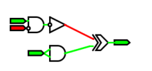
Reading this diagram: Red is false, green is true. The triangles are inverters; the blazes are OR gates (I'll pretty them up later). The flags on the right are inputs; the flags on the left are outputs. The green circles are inputs and outputs - the points where gates associate with each other. They're only shown for debugging.

More later. I promise.

Servo!

One of the final bits of this project is the servo. (A servo's a small motor that'll hold a given position.) In my case, I'm using a servo to actually turn the deadbolt. It's a little bit important.

I'd assumed that a servo's powered by the power and ground and that an analog voltage (0 or +5) on the signal line would move the servo. Surprisingly, that didn't work. It appears that the servo wants a PWM input to the signal line, even if it's just a 1% on, 99% off signal.

The Arduino has a Servo library that does all the hard work for me. I wrote a few more lines, and voila! Moving servo.

To polish the gizmo a little more, I added feedback to the reader. When an illegal key is detected, the reader blinks between red and green, beeping every 100 ms. A legal key turns on the green LED while the door's unlocked.

I also polished up the wiring. I'd been running the HID reader off of a wall wart, with a jack made of electrical tape. The Arduino, meanwhile, was depending on a computer for life support. I used a coin cell and LED as a continuity tester to wire the Arduino up the right way to the wall wart (we don't have a multimeter), and fixed up the connecting jack for better (if not good) reliability.

The entire gizmo runs on wall power, turns a servo, and remembers legal keys across reboots. All that's left is attaching the servo to the wall.

Squee.

EEP!

Previously on My Hobbies, I showcased how the Arduino could read from the cardreader. Since then, I added code to save and load cards from EEPROM. What's EEPROM, you ask? Good question!

EEPROM is an unpowered rewritable type of memory. When a program's running, the Arduino stores variables in RAM (Random Access Memory). This memory is durable for many read-write cycles, but zeroes out when power's lost. EEPROM (Electrically Erasable Programable Read Only Memory) is only good for about 100,000 read-write cycles, is fairly slow (3.3ms/read), and only stores bytes (8 bits), but retains data across reboots.

Quick aside: The name EEPROM contains a contradiction. How is memory read only and erasable?

The answer lies more in history than anything. Early PROM (Programmable Read Only Memory) chips were programmed permanently. Programming these chips burned out internal fuses (tiny wires), leaving a physically changed circuit.

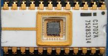
The next iteration of the chips, EPROM (Erasable Programmable Read Only Memory; image above), allowed for reprogramming. Exposing the die of the board to a UV light would reset it to an unprogrammed state.

EEPROM is a third iteration of ROMs. The Read Only restriction is long gone, but lives on in the acronym.

Opening Doors

Second post! That's a thing, right? Good.

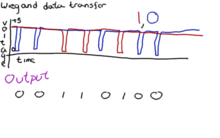
Last time, I got as far as reading out bits from the card. I noticed a few things about the output bits:

  • The first half of the code was always the same.
  • The code was around 35 bits long.

With enough cards, I could have reverse-engineered the card code, but Cyborg Mode is easier. A few quick searches turned up a site explaining the HID format. In essence, the card has two pieces of data stored on it: a 12 bit facility code (same of all Lafayette cards), and a 20-bit card code (different on each). A quick aside: 220=1,048,576, so Lafayette's 2,500 students use only a smidge of the possible combinations.

Reading Secrets

See that picture? Good. The college uses readers just like those all across campus for access control. They're on the front of all of the academic buildings, all the dorms - just about everywhere uses these phobs.

A few days ago, I bought one of them. (It's wild what you can buy on EBay. Really wild.) The reader arrived on Monday, and sat around for a while. Midway through the week, I decided to have at it.

Serenity

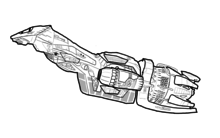
Serenity. Recognize it? Good.
I sketched this in the week I had off from school. Looks pretty cool. It's going on my door.

Pages